1. Let’s create a Library
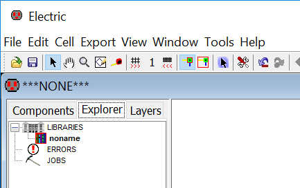
Go to Explorer (beside the Components view); you will find LIBRARIES name as noname
File –> Save Library As
Go to the location where you want to save your design (eg: $PATH/Electric/Designs)
Name the design (library name) eg. design_1.jelib
We would create our schematic and layout under this library
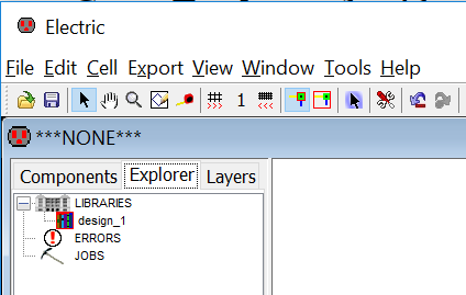
Now you will see design_1.jelib under LIBRARIES name in Explorer
2. Creating a new cell
Go to cell –> New Cell (or you can press ctrl + N). You will find a window like following.
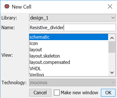
Enter the name of the cell {Resistive_divider} and click the view as {schematic}.
Press ok.
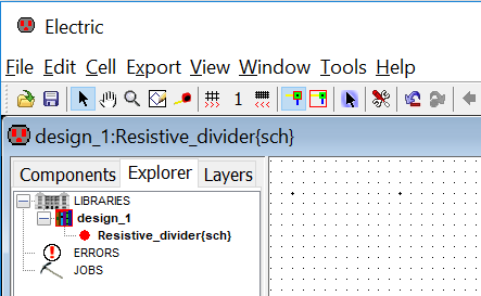
Now under the library design_1.jelib you can find a schematic cell named as Resistive_divider {sch} with a red indicator as follows.
Now Press the Components. You will find the schematic components unlike the layout components in the startup window.
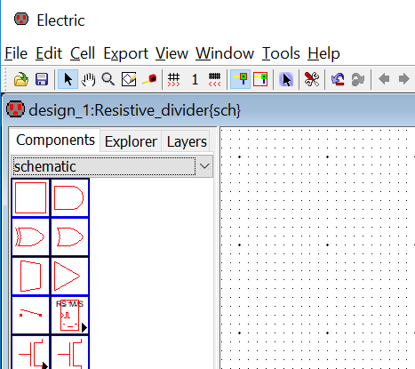
The library name and cell name are seen above the Components, Explorer (shows cells in your library), and Layers (useful in layouts).
3. Creating a Resistor Schematic
Create an N-Well schematic resistor Node by clicking the component as shown in the figure.
Place the N-Well schematic resistor Node into the drawing area (left click the mouse button to place the Node).
In Electric, a Node is a component used in a schematic or layout. Resistors, capacitors, transistors etc. are called as Nodes.
An Arc is used to establish the connection between Nodes. A wire is an example Arc in a schematic.
Go to the Window menu commands to zoom in/out, fit, etc.
Editing the Properties of the Component
Select the schematic resistor Node by moving the mouse over the Node’s highlight box and left clicking on it.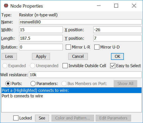
Now you can edit the properties of the component resistor by executing Edit –> Properties –> Object Properties (or by pressing Ctrl+I).
Let we have changed the width = 15, length = 187.5 and the resistance = 10K. (We will use the same values while creating the layout)
If the Well resistance is not shown then hit the More button.
Press OK to apply the changes to the Node properties. Always press OK. If you will press X, in the top right corner then the changes will be ignored.
Now you can see the resistor as follows:
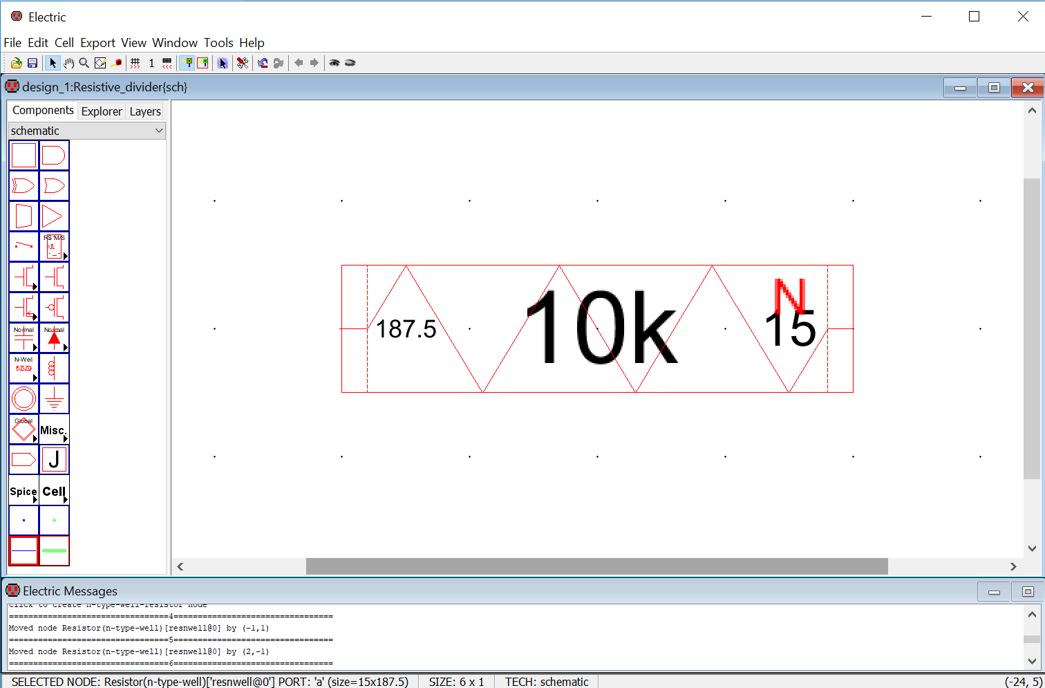
If the text inside the component node is very large, then reduce the size of the text by going to Edit -> Text -> Decrease All Text Size (or by pressing Ctrl+Minus).
Both the ports at the end of the resistor are used to connect wire while constructing a circuit.
2 comments for “Creating Resistor Schematic”