Now we would simulate the resistive divider circuit which has been built, and would observe the output voltage w.r.t. a particular input voltage.
For this we need to write a SPICE code which would give the description of the input voltage and would indicate the type of simulation we want to perform.
Writing SPICE Code
 Go to the Components menu. Click on the arrowhead in the Misc box to add SPICE code to the schematic as seen in the figure.
Place the SPICE code in the schematic and use Ctrl+I to edit its properties.
Ensure, in the SPICE code property box, that the Multi-line Text box is checked.
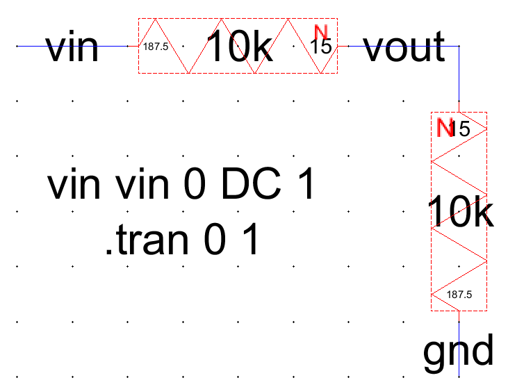
Add the code shown in the figure for specifying a SPICE transient analysis and an input voltage source. The code indicates an input voltage of 1 V DC is applied to the circuit. The analalysis would be a transient one for 1 second.
Press F5 to check the schematic.
Simulation of the Schematic
Go to Tools -> Simulation (Spice) -> Write Spice Deck.
The following LTspice window will open.
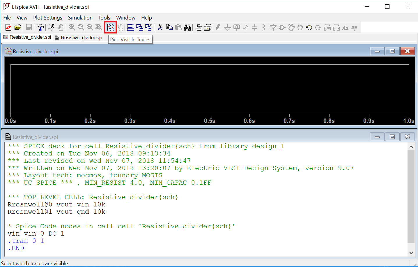
Click on the red boxed icon (Pick Visible Traces) above to show the waveforms available for plotting.
Select V(vout) and V(vin) to display as following:
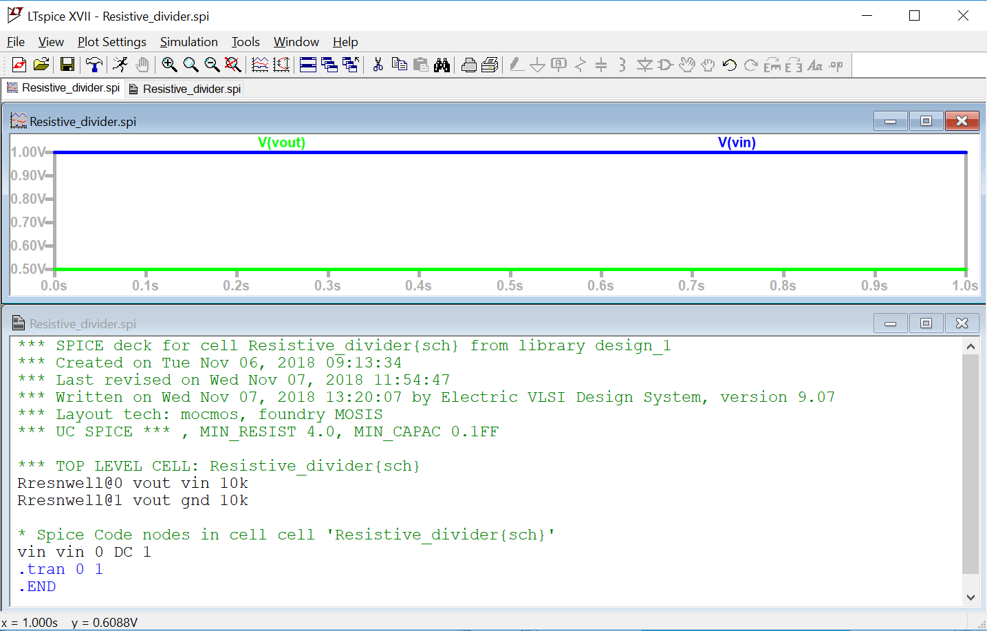
We just changed the back ground to white for better visibility.
So here you can observe that the output (vout represented in green) is 0.5 volt and the input (vin represented in blue) is 1 volt. So the output gives an equally divided voltage by two same value of resistors in our design.