Create a new cell as in case of schematic earlier with the view as {layout} and with the same cell name Resistive_divider.
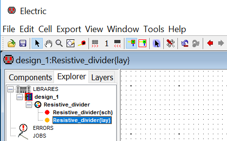
Now under the library design_1.jelib you can find a layout cell named as Resistive_divider {lay} with an yellow indicator as follows:
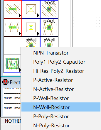
 Create an N-Well Resistor layout by clicking the menu item (bottom left-hand side of the menu) as shown in the figure in right.
If this menu item is not shown, that means you have not selected the Analog option in the preferences at the beginning of this tutorial.
Edit the properties of the component resistor as width = 15, length = 187.5 and the resistance = 10K.
If the grids in the screen are distracting, then you can toggle grid in the window by executing Window –> Toggle Grid (or by pressing Ctrl+G)
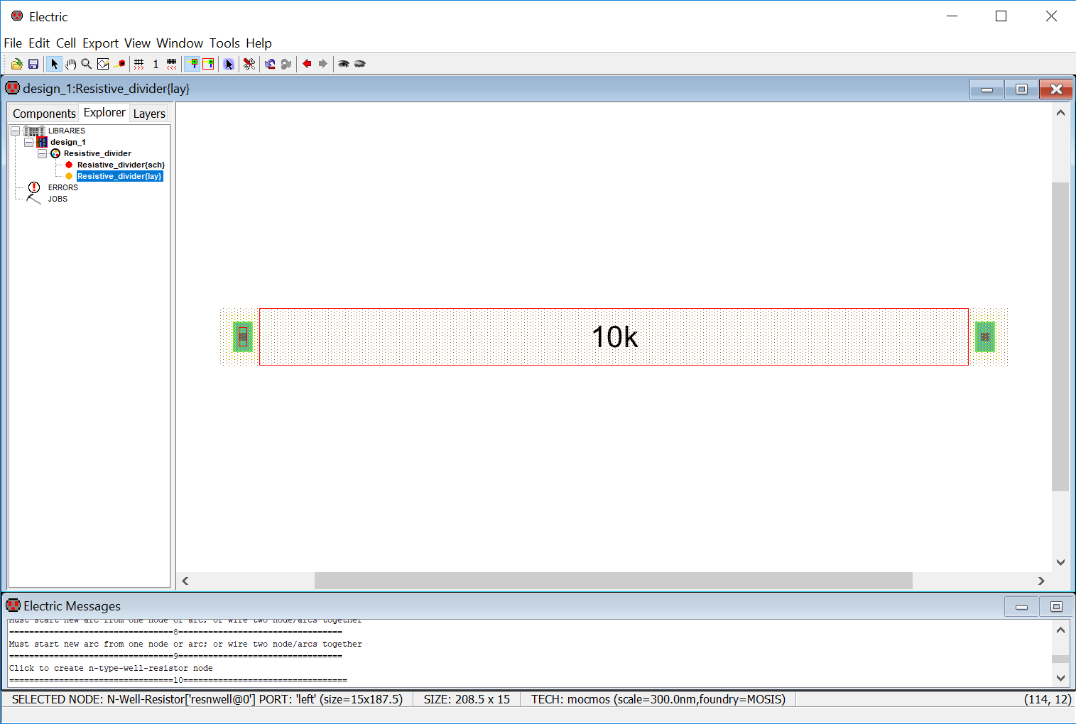
Now you can see the resistor as follows:
Bottom section of the screen indicates the technology and scale. Right corner of this section also shows the x and y position of the cursor which is useful during layout.
If the text inside the layout component node is very small, then increase the size of the text by going to Edit -> Text -> Increase All Text Size (or by pressing Ctrl+Equals).
But doing this might unusually increase the size of the text in the schematic view. So, to increase the text only in layout view, do the following:
Select the text, you want to change the size. A cross mark (X) on the text will be selected.
Change the Object Properties by pressing Ctrl+I
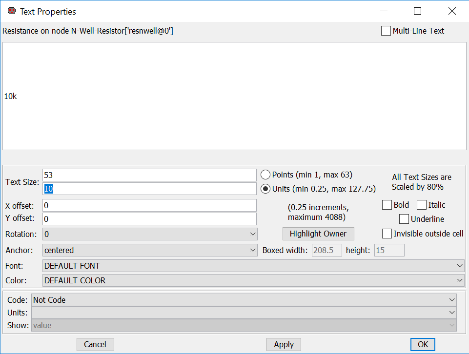
And then change the size (according to your requirement) as shown in right:
Like the schematic, we can select the layout resistor Node by moving the mouse over the Node’s highlight box and left clicking on it.
It has also two ports for Arc connection.

