State machine synthesis is a process of of boiling down a state machine to a digital logic circuit.
Steps in State Machine Synthesis
- Convert the description into state machine
- Find out the equivalent states and minimize the state machine
- Encode the states
- Chose a set of flipflops for state register
- Use the excitation table to arrive at the input specification of the combinational logic
- Synthesize the combinational logic
Let’s achieve the state machine realization of the following state diagram
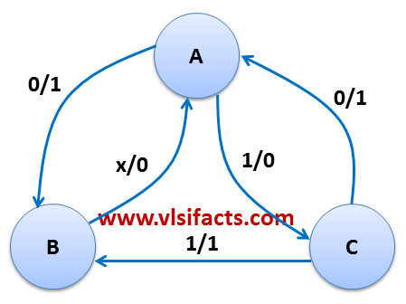
A Mealy State Machine for Synthesis
Let’s assume that we have completed the first two steps mentioned above and achieved a minimized Mealy state machine as shown above. We would synthesize this state machine using T-Flipflops.
The next step is to encode the states. For 3 states:
State Encoding
A 00
B 01
C 10
The state register will be the combination of 2 T Flipflops. Now we have to design the combinational logic which would generate the output and help generating the next state (NS).
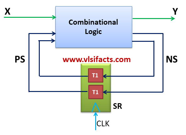
Mealy State Machine Block Diagram
Let’s draw the state transition table using the Excitation table of T flipflop
| PS
Q2(t) Q1(t) |
X
Input |
NS
Q2(t+1) Q1(t+1) |
Excite (T)
T2 T1 |
Y
Output |
| 0 0 | 0 | 0 1 | 0 1 | 1 |
| 0 0 | 1 | 1 0 | 1 0 | 0 |
| 0 1 | 0 | 0 0 | 0 1 | 0 |
| 0 1 | 1 | 0 0 | 0 1 | 0 |
| 1 0 | 0 | 0 0 | 1 0 | 1 |
| 1 0 | 1 | 0 1 | 1 1 | 1 |
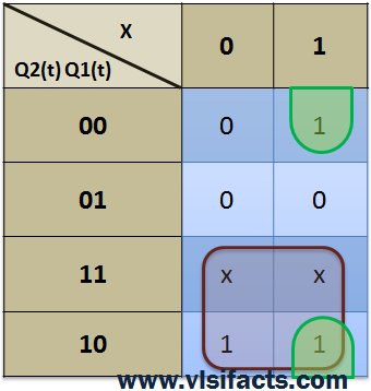
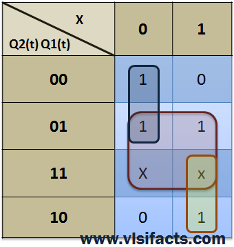
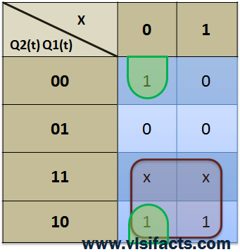
Now to realize the combinational logic we have to find out the Boolean expression for 3 output variables (of the above table) T2, T1 and Y in terms of 3 input variable Q2(t), Q1(t) and X.
| T2 | T1 |
 |
 |
| Y | Boolean Expressions |
 |
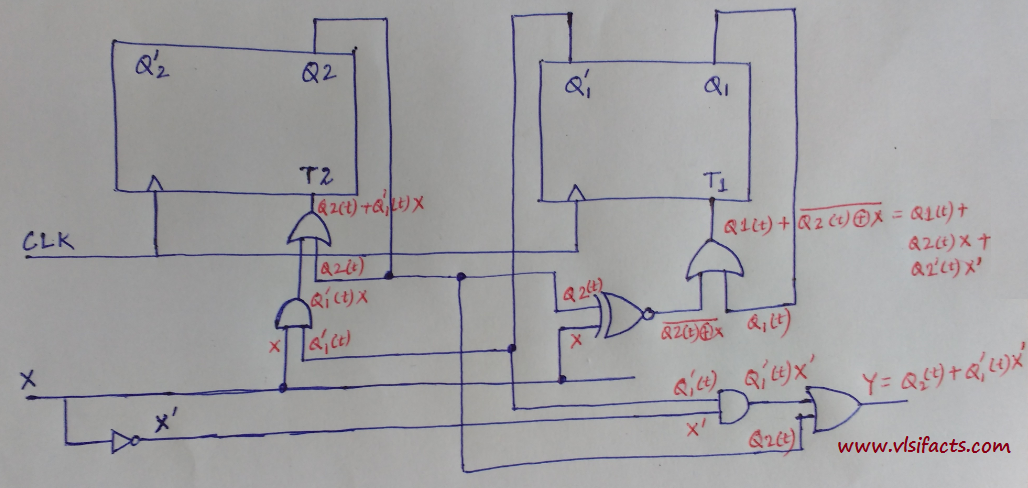
T2 = Q2(t) + Q1′(t)X
T1 = Q1(t) + Q2(t)X + Q2′(t)X’ Y = Q2(t) + Q1′(t)X’ |
Let’s draw the respective circuit diagram for the given state machine.