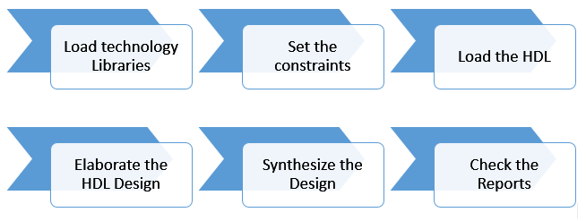
Synthesis transforms the simple RTL design into a gate-level netlist with all the constraints as specified by the designer. In simple language, Synthesis is a process that converts the abstract form of design to a properly implemented chip in terms of logic gates.
Synthesis takes place in multiple steps:
- Converting RTL into simple logic gates.
- Mapping those gates to actual technology-dependent logic gates available in the technology libraries.
- Optimizing the mapped netlist keeping the constraints set by the designer intact.
There are various tools which can be used to synthesize a design provided by various vendors including Synopsys, Cadence and Mentor Graphics.
Basic Synthesis Flow & Example:
module top (input a, input b, output c);
wire d;
assign d = a & b;
assign c = d & a;
endmodule
This contains two and gates but it will synthesize into a single AND gate after synthesis due to the optimizations performed during synthesis.
Synthesis is a very important process for the designers as it enables them to see how the design will actually look like after fabrication. All parameters including area, timing, power can be reported and checked by the designer beforehand only. He/She can make the necessary changes(if required) before the actual fabrication process, thus saving both time and cost.
