These are some simple steps which can be used to do the power analysis of a design using Xpower Analyzer which comes readily available in the ISE free web pack.
## Make sure your circuit can be synthesized. Then under the implement design option in the project navigator, Place and Route the design.
## The most common and silly error comes after the Place and Route is “the right chip is not targeted”. This is because most of the free web pack does not support the Artix family, so in the “design properties” under “family“, target another chip: Spartan 3 or Spartan 6 would be fine.
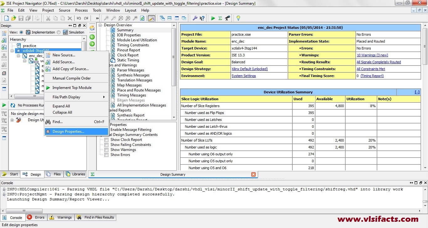
Design Properties
Step – 1
Simulate your design by using a test bench or manually. Power analysis uses the VCD (Value Change Dump) file generated by the simulator for the analysis of the switching power and then do the Placement and routing.
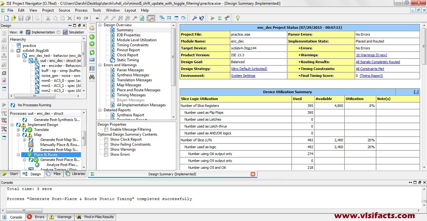
Place and Route
For VCD file generation, use the following code in your test bench.
initial begin
// Change filename as appropriate
$dumpfile ("tran_ceiver.vcd");
// Dump all the variables in VCD
$dumpvars (1,tran_ceiver_test.uut);
end
Step – 2
Under Place and Route, click on the option Analyze Power Distribution.
Step – 3
In the Xpower analyzer go to the file menu and click on the open design. A new window will appear. In that window open your design. The design file would be like “design_name”.ncd. In the Physical Constraint file, select the file “design_name”.pcf (both these files .ncd and .pcf are generated during place and route). finally in the simulation activity add the VCD file “file_name”.vcd
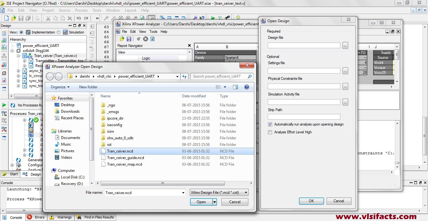
Design File (.ncd)
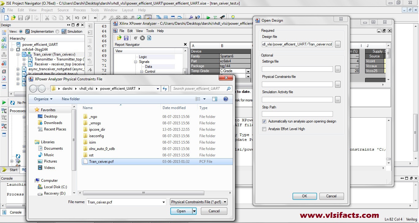
Physical Constraint File (.pcf)
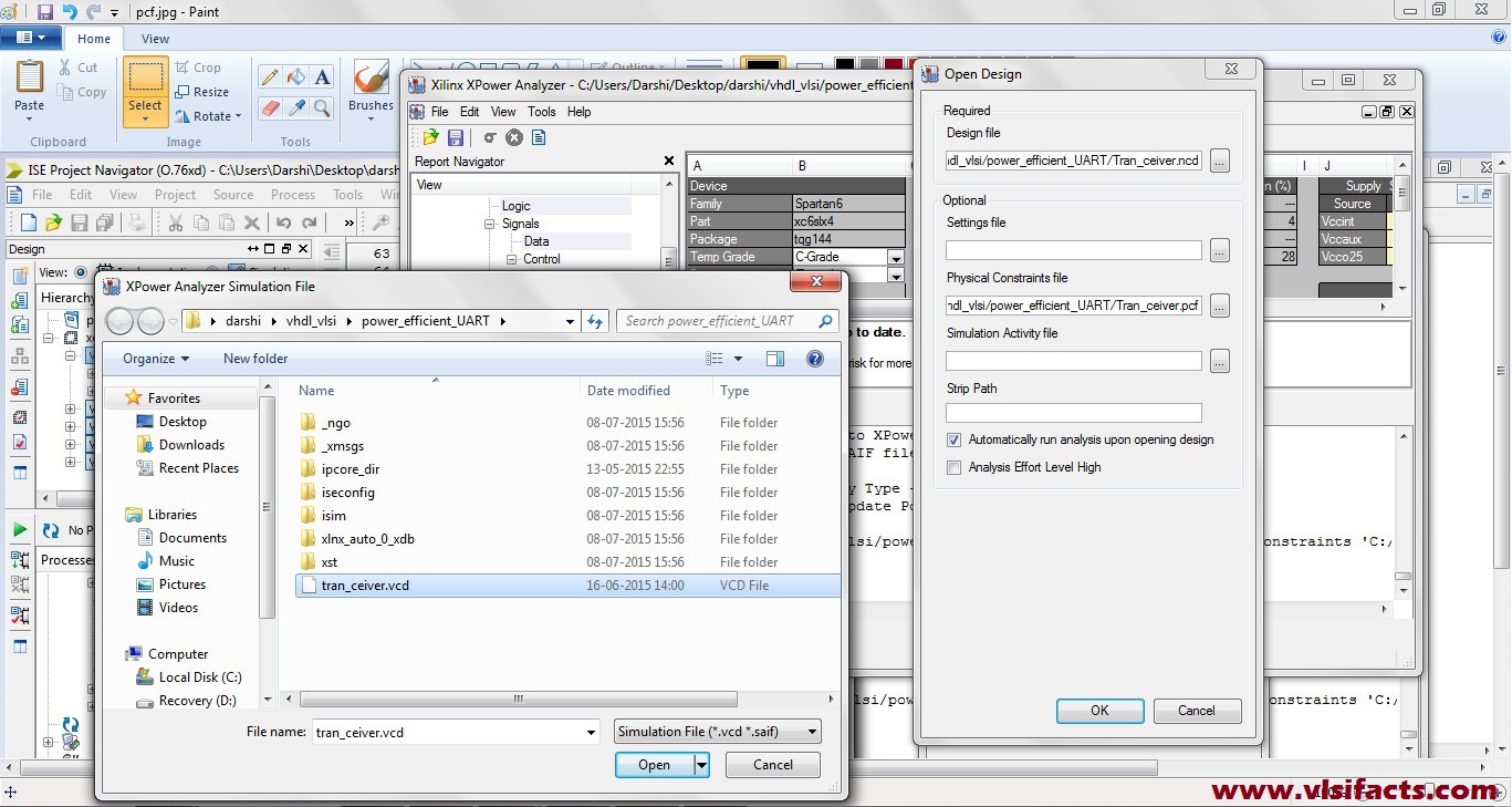
Simulation Activity File (.vcd)
Step – 4
Click “OK” and your power report will be generated.
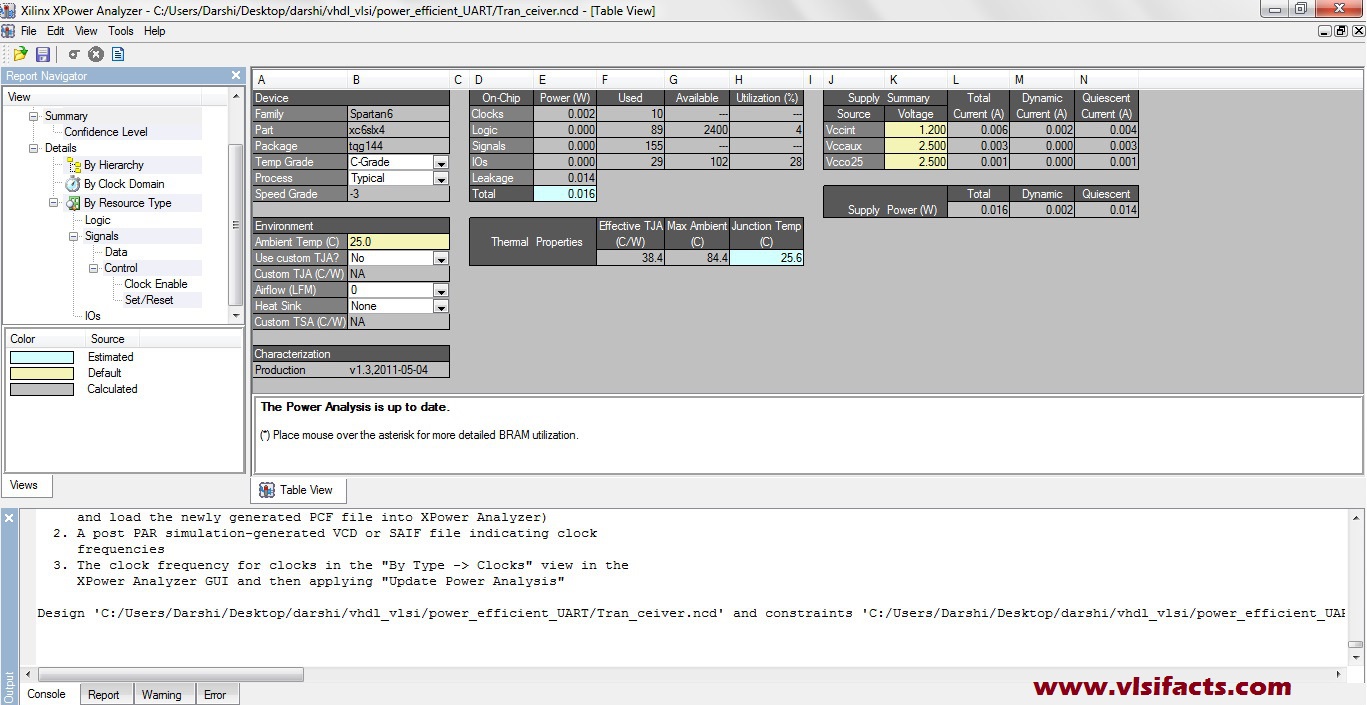
Final Power Report
7 comments for “Power Analysis in XILINX Xpower Analyzer”