Sequence Detector is a digital system which can detect/recognize a specified pattern from a stream of input bits.
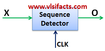
Sequence Detector Conceptual Diagram
Let’s say the Sequence Detector is designed to recognize a pattern “1101”. Consider input “X” is a stream of binary bits. When the Sequence Detectors finds consecutive 4 bits of input bit stream as “1101”, then the output becomes “1” [O = 1], otherwise output would be “0” [O = 0].
Let’s design the Mealy state machine for the Sequence Detector for the pattern “1101”.
Define 4 states
- S0: No match till time ‘t’
- S1: 1-bit match till time ‘t’
- S2: 2-bit match till time ‘t’
- S3: 3-bit match till time ‘t’
The state machine diagram would be as follows:
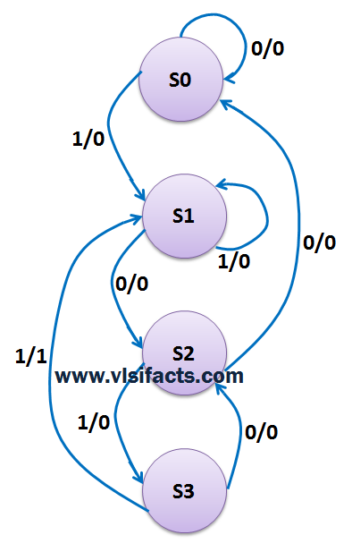
Mealy machine of “1101” Sequence Detector
Now let’s understand how we get the transitions and corresponding outputs: Keep in mind that we will move from left to right that means from LSB towards MSB
Let’s say we are at the initial state S0: No bit matched yet
for input “0”: Since the 1st bit of the pattern to be matched is “1” [LSB], so again no bit match. Hence the next state will be “S0” and the output will be “0” as the whole pattern has not been matched yet.
for input “1”: Since the 1st bit of the pattern is matched, the next state will be “S1”. But the output will be still “0” as the whole pattern has not been matched yet.
Let’s say we are at the state S1: 1st bit already matched, That means LSB “1” of the pattern “1101” already received
for input “0”: Since the “1” had been already received, now a “0” will make the sequence as “01”. So 2 bit matching, hence the next state will be “S2” and the output would be “0” as the whole pattern has not been matched yet.
for input “1”: Since the “1” had been already received, now a “1” will make the sequence as “11”. So no 2 bit matching but we can consider the recently received “1” as the 1st bit matching of a newly considered pattern “1101”. So the next state would be the same “S1” and the output will be “0”.
Let’s say we are at the state S2: 2 bits already matched, That means “01” of the pattern “1101” already received
for input “0”: Since the “01” had been already received, now a “0” will make the sequence as “001”. So pattern matching failed. Hence the next state will be “S0” and output will be “0”.
for input “1”: Since the “01” had been already received, now a “1” will make the sequence as “101”. So 3 bit matching. Hence the next state would be “S3” and the output will be “0” as no complete pattern matching yet.
Let’s say we are at the state S3: 3 bits already matched, That means “101” of the pattern “1101” already received
for input “0”: Since the “101” had been already received, now a “0” will make the sequence as “0101”. So pattern matching failed, but we can consider the recently received “01” as the 2 bit matching of a newly considered pattern “1101”. Hence the next state will be “S2” and output will be “0”.
for input “1”: Since the “101” had been already received, now a “1” will make the sequence as “1101”. So the whole pattern got matched. Hence the output will be “1” and the next state would be “S1” as we can consider the recently received “1” as the 1st bit matching of a newly considered pattern “1101”.
Check the circuit design of the above state machine diagram @ Circuit Design of a Sequence Detector