Parity generator can be of two types:
(i) Even Parity Generator
(ii) Odd Parity Generator
In this post we will derive the state machine for an even parity generator.
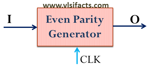
Even Parity Generator Conceptual Diagram
Consider input “I” is a stream of binary bits. When an input comes, the even parity generator checks whether the total number of 1’s received till then are even or odd. If even then the output becomes “0” [O = 0], otherwise output would be “1” [O = 1].
Let’s design the Mealy state machine for the Even Parity Generator.
Define 2 states
- S0: Number of 1’s received till now is even
- S1: Number of 1’s received till now is odd
The state machine diagram would be as follows:
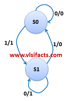
Mealy Machine for Even Parity Generator
Now let’s understand how we get the transitions and corresponding outputs:
Let’s say we are at the state S0: Even number of 1’s received yet
for input “0”: Since the present state represents that till now even number of 1’s are received, an input “0” will keep the number of 1’s received as even. So, the next state would be S0 and the output (parity bit generated) would be “0”.
for input “1”: An input “1” will make the number of 1’s received as odd. So, the next state would be S1 and the output (parity bit generated) would be “1”.
Let’s say we are at the state S1: Odd number of 1’s received yet
for input “0”: Since the present state represents that till now odd number of 1’s are received, an input “0” will keep the number of 1’s received as odd. So, the next state would be S1 and the output (parity bit generated) would be “1”.
for input “1”: An input “1” will make the number of 1’s received as even. So, the next state would be S0 and the output (parity bit generated) would be “0”.