Now we are ready to simulate the layout view off this cell.
Let’s open up the schematic view of the cell and copy the SPICE code.
Go back to the layout view and paste the SPICE code.
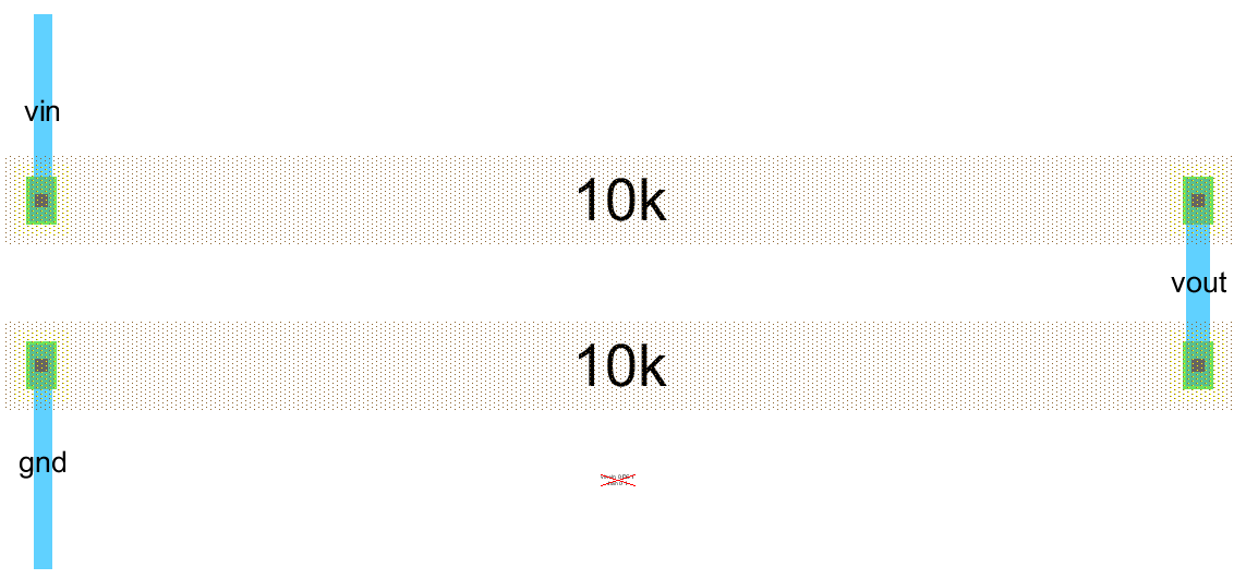
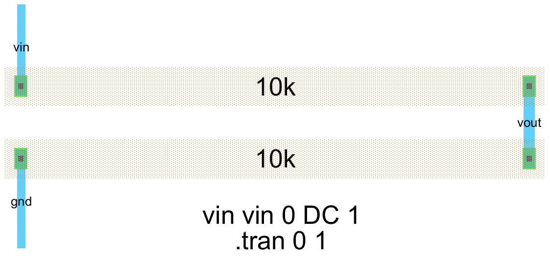
Increase the text size of the spice code to 10 by going to its object property (Ctrl+I).
The following figure shows the visible spice code.
Run a DRC, NCC, and a Well Check to ensure that there aren’t any errors.
This cell can be simulated following the same steps used for simulating the schematic view above.
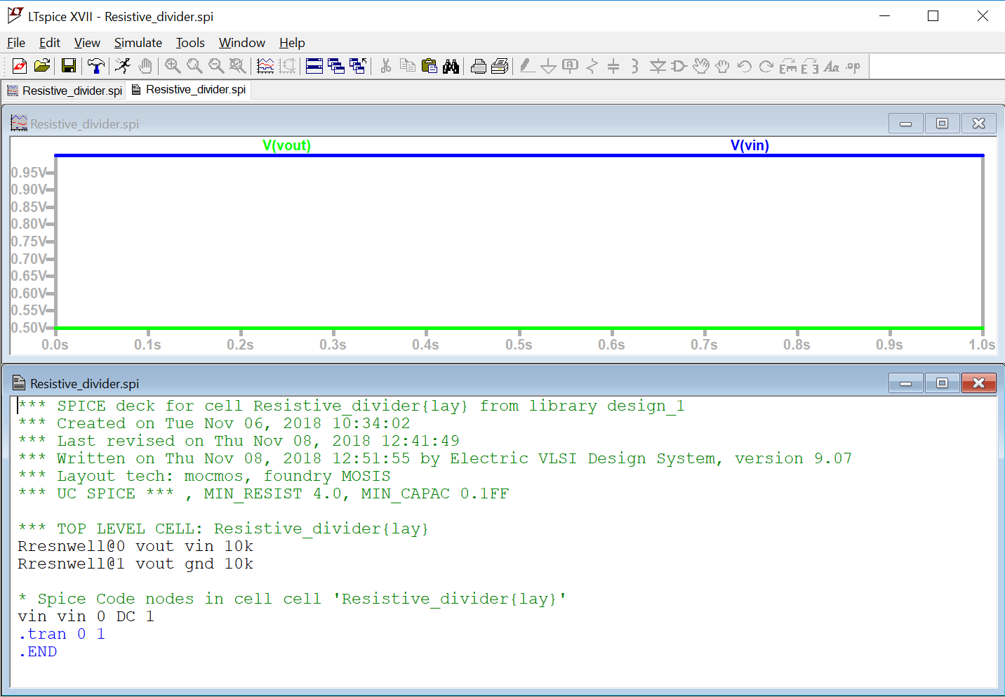
Simulate this cell using LTspice now.
The following figure shows the simulation output from LTspice for the Resistive_divider layout.
We believe this design tutorial would have helped you. Follow the tutorial and start designing from the scratch by yourself, if you are new to Electric. Remember, doing by yourself teaches you the best, and you learn more when you try to solve the problem by yourself.