A “module” is the basic building block in Verilog. A module can be an element or a collection of lower-level design blocks. A module provides the necessary functionality to the higher-level block through its port interface (inputs and outputs), but hides the internal implementation. Module interface refers, how module communicates with external world. This communication is possible through different ports such as input, output and bi-directional (inout) ports.Design functionality is implemented inside module, after port declaration. The design functionality
In Verilog, a module is declared by the keyword module. A corresponding keyword endmodule must appear at the end of the module definition. Each module must have a module_name, which is the identifier for the module, and a port list, which describes the input and output terminals of the module. Design functionality is implemented inside module, after port declaration. The design functionality implementation part is represented as “body” here.
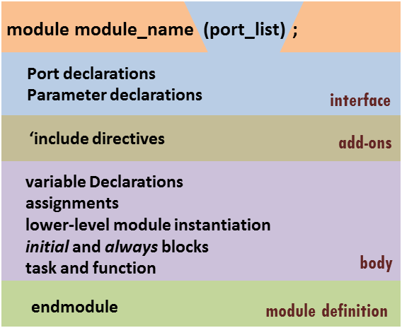
Module definition: A module is enclosed between module and endmodule keywords. Also, the name of the module and a semicolon are mandatory. Module definitions can not be nested.
Interface: It consists of up to three optional elements: port list enclosed in brackets, port declarations for each port from the port list and parameter declarations. The interface must be declared before the module body.
Add-on: Any additional specifications can be inserted into the code using ‘include compiler directive with the file name enclosed in double quotes – one directive per file. The ‘include directive can be used anywhere in the code.
Module body: The five elements of the body specification can be used in any sequence with only one restriction – no item can be used before it is declared.
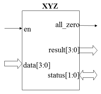
module XYZ (en, data, all_zero, result, status);  // XYZ is the module name
  input        en;        // scalar input
  input  [3:0] data;      // vector input
  output       all_zero;  // scalar output
  output [3:0] result;    // vector output
  inout  [1:0] status;    // bi-directional port

<body>
endmodule
- To make code easy to read, use self-explanatory port names.
- For the purpose of conciseness, use short port names.
- If port is vector, we can represent it in ‘2’ different ways. For output port “result” we can represent it as [3:0] or [0:3]
The module name
The module name, formally called an identifier should best describe what the system is doing. Each identifier in Verilog, including module names must follow these rules:
- It can be composed of letters, digits, dollar sign ($), and underscore characters (_) only.
- It must start with a letter or underscore.
- No spaces are allowed inside an identifier.
- Upper and lower case characters are distinguished (Verilog is case sensitive)
- Reserved keywords cannot be used as identifiers.
Ex: Counter_4Bit, ALU, Receiver, UART_Transmit
2 comments for “Module Definition in Verilog”