Verilog language has the capability of designing a module in several coding styles. Depending on the needs of a design, internals of each module can be defined at four level of abstractions. Irrespective of the internal abstraction level, the module would behave exactly in the similar way to the external environment. Following are the four different levels of abstraction which can be described by four different coding styles of Verilog language:
- Behavioral or Algorithmic level
- Dataflow level
- Gate level or Structural level
- Switch level
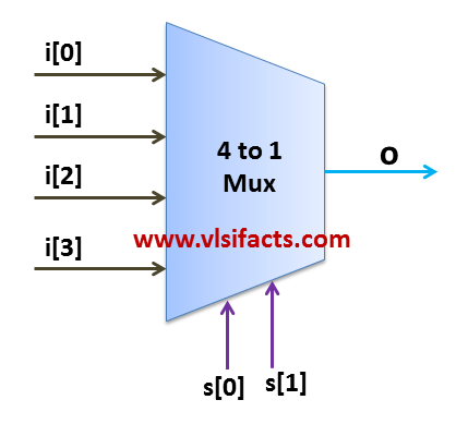
The order of abstraction mentioned above are from highest to lowest level of abstraction. The top three would be explained using a 4:1 mux.
Behavioral or Algorithmic level
- This is the highest level of abstraction provided by Verilog HDL.
- A module can be implemented in terms of the desired design algorithm without concern for the hardware implementation details.
- It specifies the circuit in terms of its expected behavior.
- It is the closest to a natural language description of the circuit functionality, but also the most difficult to synthesize.
Mux 4:1 Behavioral Model
module Mux_4to1(
   input [3:0] i,
   input [1:0] s,
   output reg o
);

always @(s or i)
begin
   case (s)
      2'b00 : o = i[0];
      2'b01 : o = i[1];
      2'b10 : o = i[2];
      2'b11 : o = i[3];
      default : o = 1'bx;
   endcase
end
endmodule
The output port is declared as data type “reg”. Combination of “always” block and “case” procedural statement is used to implement the multiplexer. All inputs are added as part of the sensitivity list. Select signal “s” is used as condition here. Based on value of select signal “s”, any one of the input signal will be selected. Here we are implementing the functionality of multiplexer at higher-level of abstraction without looking into internal details of the design as in “Structural Modeling”
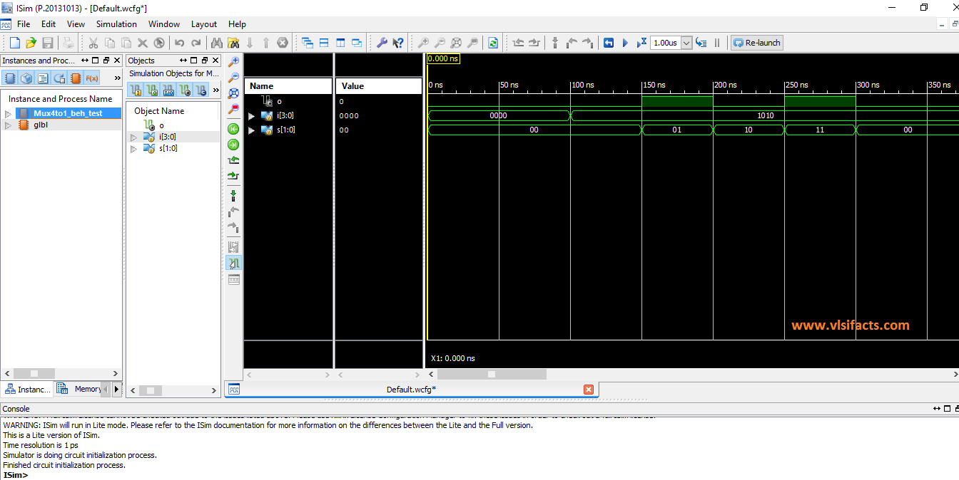
Simulation Result of 4:1 Mux Behavioral level model:
Dataflow level
- At this level, the module is designed by specifying the data flow.
- Looking towards this design, one can realize how data flows between hardware registers and how the data is processed in the design.
- This style is similar to logical equations. The specification is comprised of expressions made up of input signals and assigned to outputs.
- In most cases, such an approach can be quite easily translated into a structure and then implemented.
Mux 4:1 Dataflow Model
module Mux_4to1_df(
input [3:0] i,
input [1:0] s,
output o
);

assign o = (~s[1] & ~s[0] & i[0]) | (~s[1] & s[0] & i[1]) | (s[1] & ~s[0] & i[2]) | (s[1] & s[0] & i[3]);
endmodule
In this approach “assign” statement is used. Assign statement is a continuous statement where in any changes in signals on right hand side will update the output signal. Any changes in the input signals will execute the assign statement and the updated value will be reflected on the output “o”. Changes in the inputs are continuously monitored.
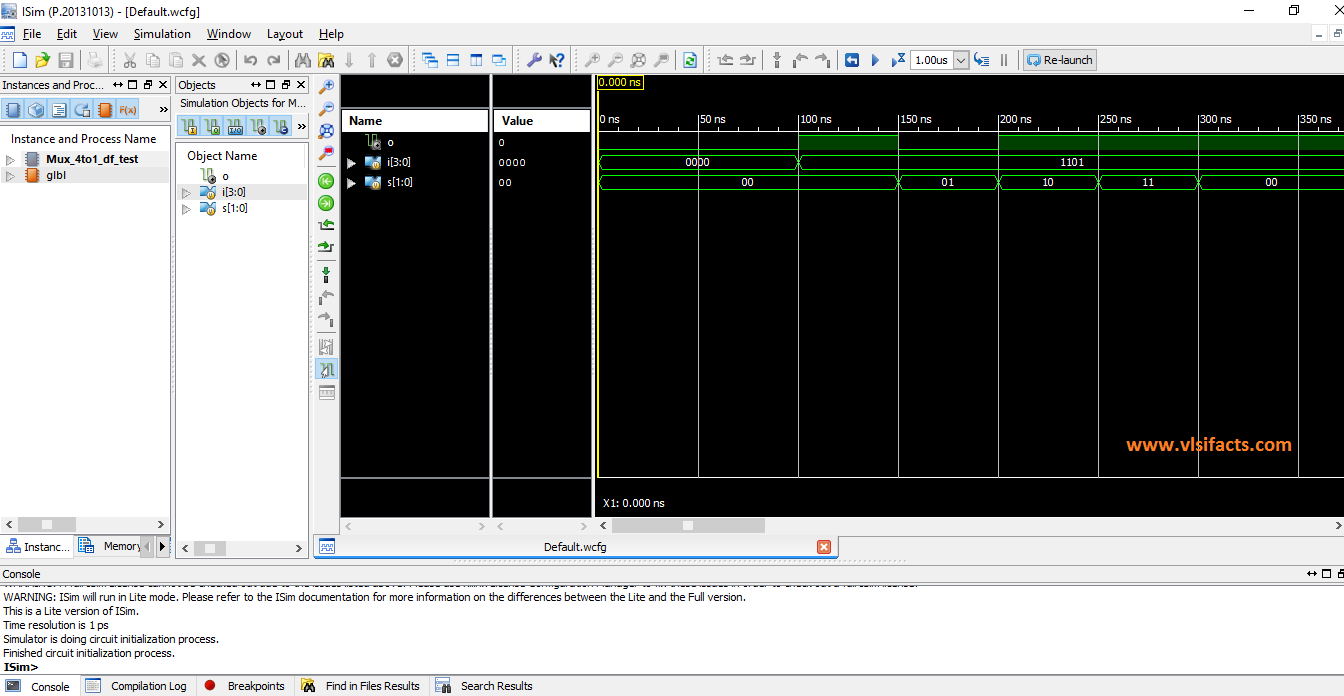
Simulation Result of 4:1 Mux Dataflow level model:
Gate level or Structural level
- The module is implemented in terms of logic gates and interconnections between these gates.
- It resembles a schematic drawing with components connected with signals.
- A change in the value of any input signal of a component activates the component. If two or more components are activated concurrently, they will perform their actions concurrently as well.
- A structural system representation is closer to the physical implementation than behavioral one but it is more involved because of large number of details. Since logic gate is most popular component, Verilog has a predefined set of logic gates known as primitives. Any digital circuit can be built from these primitives.
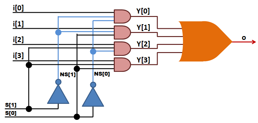
Mux 4:1 Structural Model
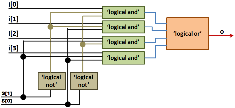
module Mux_4to1_gate(
input [3:0] i,
input [1:0] s,
output o
);

wire NS0, NS1;
wire Y0, Y1, Y2, Y3;
not N1(NS0, s[0]);
not N2(NS1, s[1]);
and A1(Y0, i[0], NS1, NS0);
and A2(Y1, i[1], NS1, s[0]);
and A3(Y2, i[2], s[1], NS0);
and A4(Y3, i[3], s[1], s[0]);
or O1(o, Y0, Y1, Y2, Y3);
endmodule
In this approach, the multiplexer is represented in gate-level representation. It consists of ‘4’ AND gates, ‘2’ NOT gates and ‘1’ OR gate. Intermediate signals “NS1”, “NS0”, “Y3”, “Y2”, “Y1”, and “Y0” are declared as wires. In this AND, OR and NOT gates are basic Verilog inbuilt primitives. These primitives are instantiated and connected in such a way, to get the functionality of multiplexer. This type of modeling of multiplexer is known as “Structural Modeling”. In this internal details of the circuit are known to model it.
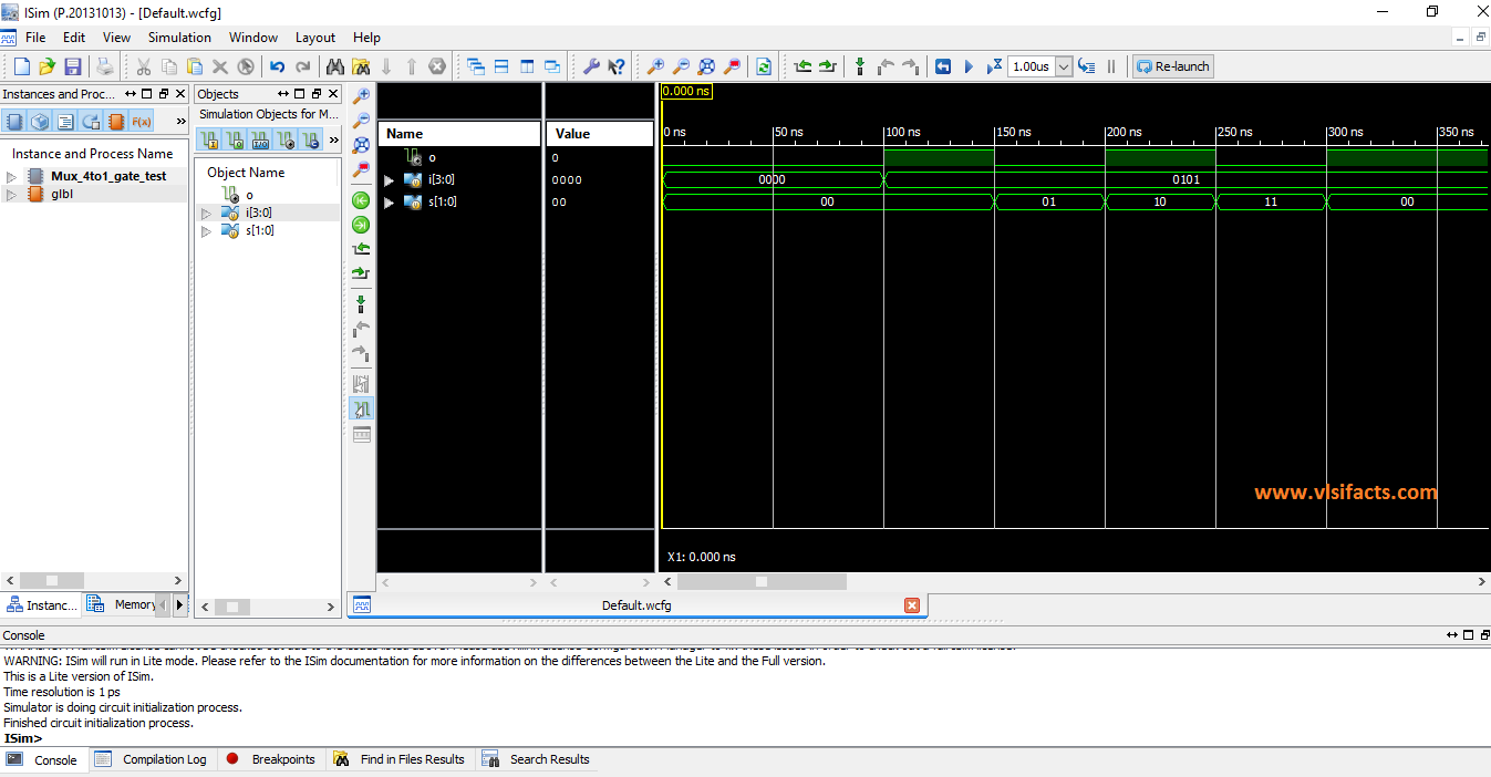
Simulation Result of 4:1 Mux Gate level model:
Switch level
- This is the lowest level of abstraction provided by Verilog.
- A module can be implemented in terms of transistors, switches, storage nodes, and the interconnections between them.
- In Verilog HDL transistors are known as Switches that can either conduct or open.
- Design at this level requires knowledge of switch-level implementation details.
Verilog supports design that can be represented in different modeling levels. Describing the design at different levels is known as Mixed-level Modeling. Simulating the design consisting of different modeling levels is known as Mixed-level Simulation.
Reference: Verilog HDL, A guide to Digital Design and Synthesis; Samir Palnitkar
4 comments for “Different Coding Styles of Verilog Language”